motherboard-schematic-and-boardview-guide
What Is a Motherboard Schematic and BoardView? A Complete Guide for Repair Technicians
Modern laptop and desktop motherboard repair is no longer possible with guesswork alone. As motherboards become more complex, technicians need accurate technical documentation to diagnose faults quickly and safely. Two of the most important resources used worldwide are Motherboard Schematics and BoardView files.
This article is a complete, technician‑friendly guide that explains what schematics and BoardView files are, how they work together, and how they are used in real‑world motherboard repair. This guide is written in a model‑independent way, so it applies to GIGABYTE-GA-B150M-D3H REV 1.0 as well as many other laptop and desktop motherboards.
What Is a Motherboard Schematic?
A motherboard schematic is a technical circuit diagram that shows how all electronic components on a motherboard are electrically connected. It is similar to an electrical blueprint used by engineers during the design and manufacturing process.
A schematic does not show the physical location of components. Instead, it focuses on:
- Electrical connections
- Signal flow
- Power distribution
- Component values and reference designators
For repair technicians, the schematic acts as a roadmap for understanding how the board works internally.
Key Information Found in a Schematic
A complete motherboard schematic typically includes:
1. Power Rails
Power sections are usually divided into different voltage rails such as:
- VIN / Adapter input
- +19V main rail
- +5VALW / +3VALW (always-on power)
- CPU Vcore
- GPU Vcore
- RAM power rails
By following these rails, technicians can quickly locate power loss, short circuits, or unstable voltages.
2. Functional Blocks
Schematics are organized into logical blocks, including:
- Charging circuit
- Embedded Controller (EC)
- BIOS circuit
- CPU power stage
- RAM interface
- USB, HDMI, LAN, and audio circuits
Understanding these blocks helps isolate which section is responsible for a specific fault.
3. Signal Lines
Important signals such as:
- Enable signals (EN)
- Power-good signals (PG)
- Clock signals
- Reset lines
These signals determine whether a motherboard can start, shut down, or enter sleep states.
How Technicians Use Schematics in Repair
In real repair scenarios, schematics are used to:
- Trace missing voltage problems
- Identify shorted components
- Check correct resistor and capacitor values
- Verify EC and BIOS connections
- Understand startup sequence logic
Without a schematic, troubleshooting becomes slow and risky. With a schematic, repair becomes systematic and predictable.
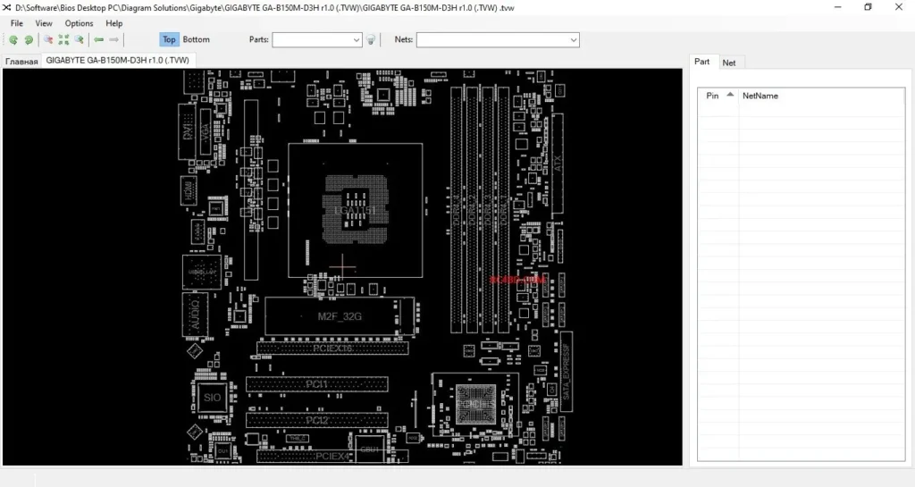
What Is a BoardView File?
A BoardView file is a visual map of the motherboard layout. Unlike schematics, BoardView shows the exact physical location of components on the PCB.
BoardView files are opened using software such as:
- OpenBoardView
- BoardView Editor
- FlexBV
These tools allow technicians to click on any component and instantly see:
- Component name (R, C, Q, U, etc.)
- Net name
- Connected pins
- Related components
Why BoardView Is Essential for Modern Repairs
While schematics explain how a circuit works, BoardView answers a different question:
“Where exactly is this component on the board?”
This is critical because modern motherboards:
- Use very small SMD components
- Have multiple layers
- Contain thousands of parts
BoardView saves time by eliminating guesswork and repeated probing.
Schematic vs BoardView: Key Differences
| Feature | Schematic | BoardView |
|---|---|---|
| Shows electrical logic | Yes | No |
| Shows physical location | No | Yes |
| Best for understanding circuits | Yes | Limited |
| Best for finding components | No | Yes |
Professional technicians always use both together.
How Schematics and BoardView Work Together
The real power comes from using both tools at the same time:
- Identify the faulty circuit using the schematic
- Note the component reference (example: R123, PU5)
- Open BoardView
- Search the reference
- Locate the exact component on the motherboard
- Measure, repair, or replace
This workflow significantly reduces repair time and error rate.
Common Motherboard Problems Solved Using These Files
Schematics and BoardView are commonly used to fix:
- No power issues
- Short circuit on main rail
- Laptop not charging
- No display problems
- BIOS corruption
- Dead USB or HDMI ports
- Overheating and shutdown issues
These files are especially valuable for Gigabyte GA-B150-D3H REV 1.0 and similar platforms.
Limitations and Important Notes
While extremely helpful, technicians should remember:
- Some schematics may be incomplete or outdated
- BoardView files may have missing nets
- Manufacturer revisions may differ
Always verify measurements on the real board.
Who Should Use Schematics and BoardView?
These tools are ideal for:
- Laptop repair technicians
- Desktop motherboard repair specialists
- Electronics engineers
- Advanced hobbyists
Beginners can also learn faster by studying these documents alongside practical repair work.
Final Thoughts
Motherboard schematics and BoardView files are not optional tools anymore — they are essential for professional-level motherboard repair. Together, they provide both the logical understanding and the physical mapping required to diagnose and fix complex faults efficiently.
Whether you are working on GIGABYTE-GA-B150M-D3H REV 1.0 or any other motherboard, mastering these tools will greatly improve your repair success rate and confidence.
This article is part of our technical documentation series. More model‑specific schematic and BoardView guides will be added regularly.